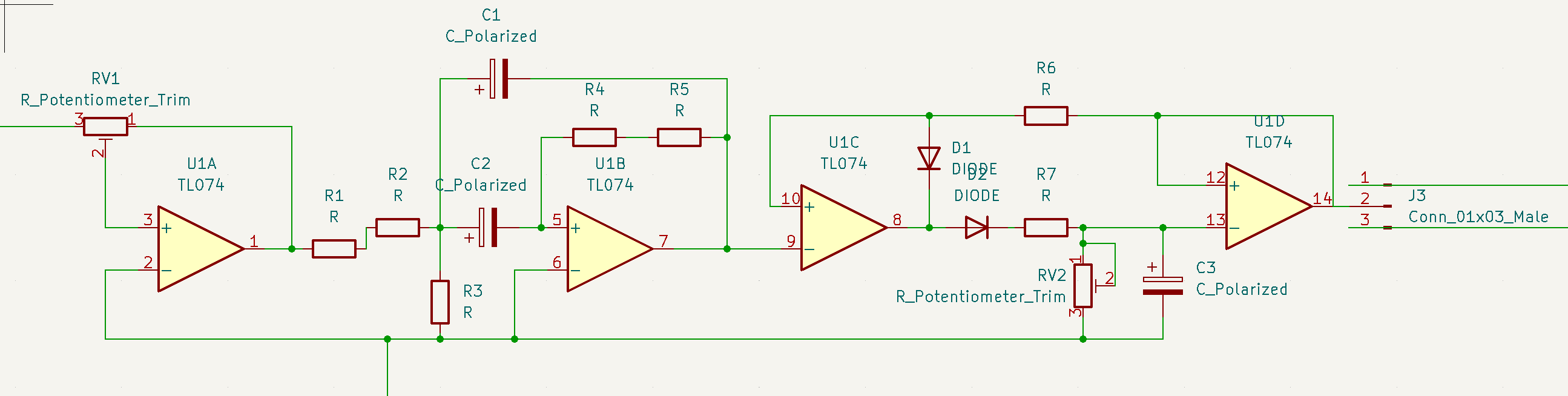
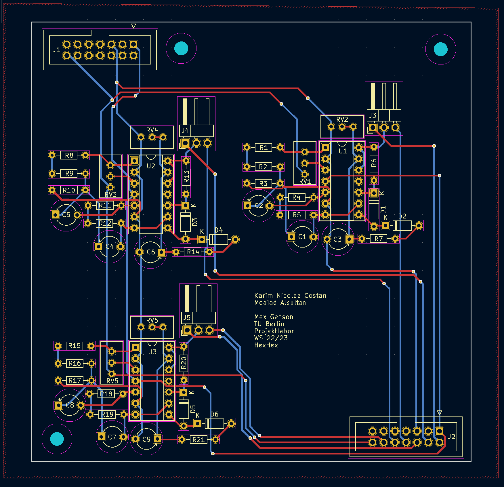
A reinvention of the MSGEQ7 chip on an PCB. The chip itself is very hard to find nowadays and they have the tendency to be faulty, so I have tried reconstructing the logic on a PCB as part of the “Projektlabor” course at the TU Berlin. It was my first PCB project, but is currently being reworked to be up to the quality of my current projects. The final result is designed to be a plug and play solution for different light set ups.
The MSGEQ6 PCB uses six Bandpassfilters and six peak detectors to capture the intensitiy of their frequency band within a given audiosignal. Within the larger context of the “Projektlabor” course, these signals of intensity were fed into an Arduino and used as references to light up LED strips. The larger the intensitiy of a given frequency band, the brighter the LEDs shone.
In the reworked version of the MSGEQ6 PCB, the evaluation done by the arduino, as well as the receiving of the audio signal will be done on the same board. I also plan to have the “output” use the DMX protocol, so it can be used for larger setups, but for now I will stick to LED strips that are directly connected to the board.